

Preserving active-element performance
Unifold is a patent-pending family of kirigami articulated shell structures developed by Degrees of Freedom LLC. This document focuses specifically on space applications of the technology: deployable solar arrays, radiators, antennas, and related apertures.
The starting premise is that active elements of deployable space structures already meet or exceed the performance needed for attractive platform economics. For example, at gigawatt manufacturing scale, the lowest-cost solar blankets made with existing commoditized technologies can exceed 240 W/kg and 320 kW/m³ at a cost below $1/W. The relevant baseline includes photovoltaic material and sufficient coverings for environmental stability—not a bare cell stripped of the layers required to operate.
| Metric | Solar blanket | Integrated satellite platform objective |
|---|---|---|
| Mass-specific power | >240 W/kg | >100 W/kg |
| Volumetric power density | >320 kW/m³ | >50 kW/m³ |
| Cost | <$1/W at GW scale | <$1,000/kg |
These capabilities provide practical paths to integrated satellite platform power densities above 100 W/kg and 50 kW/m³, with platform costs below $1,000/kg. Reaching those platform objectives requires preserving the constituent performance through integration. The technical miracle is preserving the integrity of these metrics as the active elements are converted into a functioning satellite platform.
Deployment and support hardware can erode the mass and volumetric power density of the active stack by roughly 80%. In this framing, the pressure to pursue more exotic materials or constructions comes from an inability to preserve existing active-element performance through assembly. Preserving more of that performance allows the capabilities of the active material to carry through to the assembled system.
The Unifold family uses kirigami z-folding to place deployment kinematics and structural geometry within the active aperture. Inboard disruptions of the major crease axes turn a thin blanket into a surface with finite section depth, reducing the need for separate support members and deployment mechanisms. Its design objective is to approach the flat-blanket-only mass and volume ideal to within 20%.
The system metrics celebrate the active surface doing the work. The solar blanket generates power, the radiator rejects heat, and the antenna performs its electromagnetic function. Unifold’s contribution is to minimize the non-active footprint and the mass, volume, and cost needed to assemble and deploy those surfaces. The figures express how much of the active element’s performance survives integration; they are not a claim of inherent superiority of the architecture. The same principle applies to any active surface, regardless of solar technology in the photovoltaic examples: let everything else get out of the way so the array, radiator, or antenna can do its job.
The ideal surface and the cost of arranging it
The ideal system remains a perfectly flat active surface floating in space. Unifold will always be inferior to that ideal in preserving active-element performance: its geometric and mechanical provisions consume some of the mass, volume, area, or cost available to the active surface. Their purpose is to make the surface’s arrangement more deterministic under finite loads and movement, both locally, in the relative positions and orientations of its elements, and globally, in the shape and orientation of the aperture.
The first design question is therefore how much self-arrangement the surface actually needs to provide. Careful consideration should be given to relieving the array of that requirement through the mission configuration, operating conditions, and permitted motion. Unifold is justified where the remaining need for deterministic arrangement warrants its performance penalty. Any means used to relieve the surface of that burden must be evaluated at the complete-system level.
Active surface fraction as a performance measure
Treating the assembly as a surface structure simplifies the performance accounting. If active and inactive regions have comparable thickness and material density—and therefore comparable volume and mass per unit area—the inactive surface fraction becomes a direct measure of assembly overhead. Active surface fraction then provides a first-order estimate of how much of the active stack’s mass and volumetric performance the assembly preserves.
First-order relationship: active surface fraction = active area / total assembly surface area. With equal mass per unit area, unchanged output per active area, and negligible additional hardware, assembly W/kg = active-stack W/kg × active surface fraction. The analogous W/volume relationship also requires comparable thickness and efficient stowed packing.
The approximation is most useful when the design keeps those assumptions physically credible. Differences in regional thickness or density, unused packing volume, and discrete hardware must be included when they become significant. The goal is to make geometric area allocation a useful performance indicator, so the cost of a crease pattern or structural feature is visible directly in the surface layout.
Making the zero-thickness model physically relevant
Active-stack thicknesses are dramatically smaller than the bounding dimensions of the facets. That scale separation permits the crease pattern to be treated as zero thickness for first-order kinematic design, bringing normally theoretical origami and kirigami geometry close to the physical configuration. Thickness remains finite for mass, volume, joint design, and local interference; it can be neglected in the geometric model without being discarded from the performance accounting.
A common model across disciplines
Reducing the number of independent variables makes both design and evaluation more tractable. A surface-based architecture connects crease geometry, active-area allocation, packing, deployment, and structural section without requiring a separate support system to be redesigned for every pattern. Candidate designs can be compared more objectively because their geometric changes map more directly to performance erosion.
The same abstraction makes the design transferable between disciplines. Crease-pattern research supplies geometric and kinematic methods; shell and structural mechanics address section stiffness and stability; active-element technologies supply functional stacks and environmental protection. A common surface model allows established solutions from these fields to address difficult parts of the same assembly, while keeping the remaining integration problems explicit.
Benchmarking assembly performance
A common active-surface baseline makes the integration penalty visible. The calculations below use 1 kg/m² areal mass, 0.7 mm stack thickness, and 225 W/m² electrical output. These assumptions describe the active stack, including its environmental coverings.
| Quantity | Value | Calculation |
|---|---|---|
| Areal mass | 1 kg/m² | Assumed |
| Stack thickness | 0.7 mm | 0.0007 m |
| Electrical output per area | 225 W/m² | Assumed |
| Mass-specific power | 225 W/kg | 225 / 1 |
| Volumetric power density | 321.4 kW/m³ | 225 / 0.0007 / 1,000 |
This calculation baseline is distinct from the broader >240 W/kg commodity-blanket capability discussed above. It fixes one consistent set of assumptions for comparing how much active-surface performance is retained through assembly. The solar technology supplies the baseline performance; minimizing non-active overhead preserves a larger fraction of it. That benefit is not specific to the solar technology used in this example.
Pantograph boom and blanket benchmark
K2 Space promotional photographs and video captures provide a visual reference for a pantograph boom and blanket architecture. The annotated geometry is used here to estimate the fraction of the stowed envelope occupied by active blanket material. The volume estimate combines the relative projected areas of the stowed blanket assembly and boom with the folded-blanket-to-assembly thickness ratio. It yields an estimated active volume fraction of approximately 12%. A separate rule-of-thumb assumption assigns 25% of assembly mass to the blanket. [7]

| Architecture | Active mass fraction | Active volume fraction | W/kg | kW/m³ |
|---|---|---|---|---|
| Active stack alone | 100% | 100% | 225 | 321.4 |
| Boom and blanket benchmark | 25% | 12% | 56.25 | 38.57 |
| 2A Unifold model | 90% | 81% | 202.5 | 260.4 |
The benchmark calculations are 225 × 0.25 = 56.25 W/kg and 321.4 × 0.12 = 38.57 kW/m³. These are author estimates based on imagery and assumed fractions, not published K2 performance specifications. The source treats the benchmark as approximately 56 W/kg and 38 kW/m³ or less. The comparison concerns deployable apertures; the integrated satellite platform must also account for its other subsystems.
Structural rationale and pattern architecture
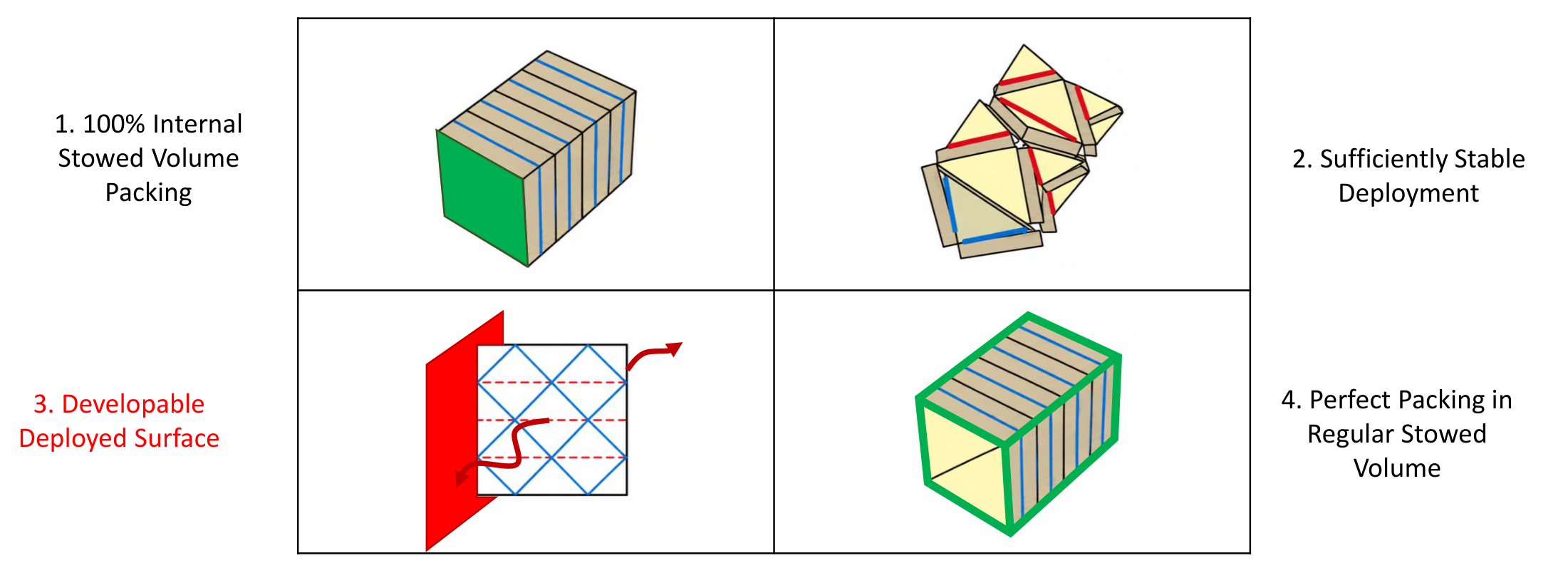
Where an aperture must maintain a prescribed arrangement under finite loads or movement, it must pack efficiently, deploy without tangling, and acquire sufficient deployed stiffness. The required stiffness follows from that arrangement requirement; it is not an objective independent of the active surface’s function. The desired combination is complete internal stack packing, complete external packing within a regular bounding volume, a one-degree-of-freedom or non-tangling deployment path, and a prescribed non-developable deployed surface. Regular active regions, fabrication from a flat sheet, and the absence of offset hinges make that combination practical.
Section depth throughout the surface
For the thin-membrane apertures considered here, developability is a structural problem. A developable region can deform through local bending of the membrane itself; at these thicknesses, that bending resistance is too small to provide useful structural stiffness.
An overall three-dimensional shape is not sufficient. Even a locally developable path can leave a continuous line along which the surface responds in bending. A fully non-developable deployed surface provides finite section depth throughout the surface, rather than only in selected regions. That section can be used for stiffness without relying on the membrane’s own local bending resistance.
From a straight crease to an inboard disruption
The geometric progression starts with a z-fold, introduces the crease disruption associated with an eggbox, and then brings the disruption inboard to form Unifold. The resulting arrangement combines the packing advantages of the z-fold with a controlled, structurally shaped deployment.

| Requirement | Z-fold | Eggbox | Unifold |
|---|---|---|---|
| 100% packing of active surface stack | Yes | Yes | Yes |
| 1-DOF or non-tangling deployment | No | Yes | Yes |
| Prescribed non-developable surface | No | Yes | Yes |
| 100% packing in regular bounding volume | Yes | No | Yes |
| Regular active surface shapes | Yes | Yes | Yes |
| Fabrication from a flat sheet | Yes | No | Yes |
| No offset joints | Yes | Yes | Yes |
The packing targets describe ideal geometry. Clearances, finite thickness, joints, and application-specific hardware must still be accommodated in a physical assembly. The prior-design comparisons later in this document show where alternative patterns satisfy or miss these requirements.
Geometry and deployment mechanics
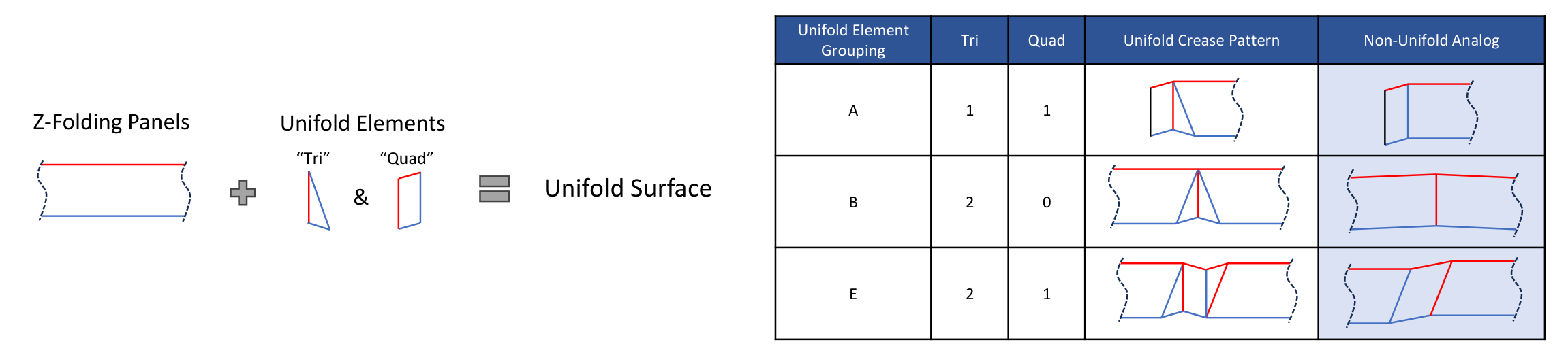
The articulated shell is defined by crease patterns assembled from triangular Tri and quadrilateral Quad elements. A group contains at least two elements, including at least one Tri, and is installed between major axes to create at least one major-axis disruption. Groups provide a common vocabulary for specifying a surface while allowing its section, curvature, and deployment path to vary.
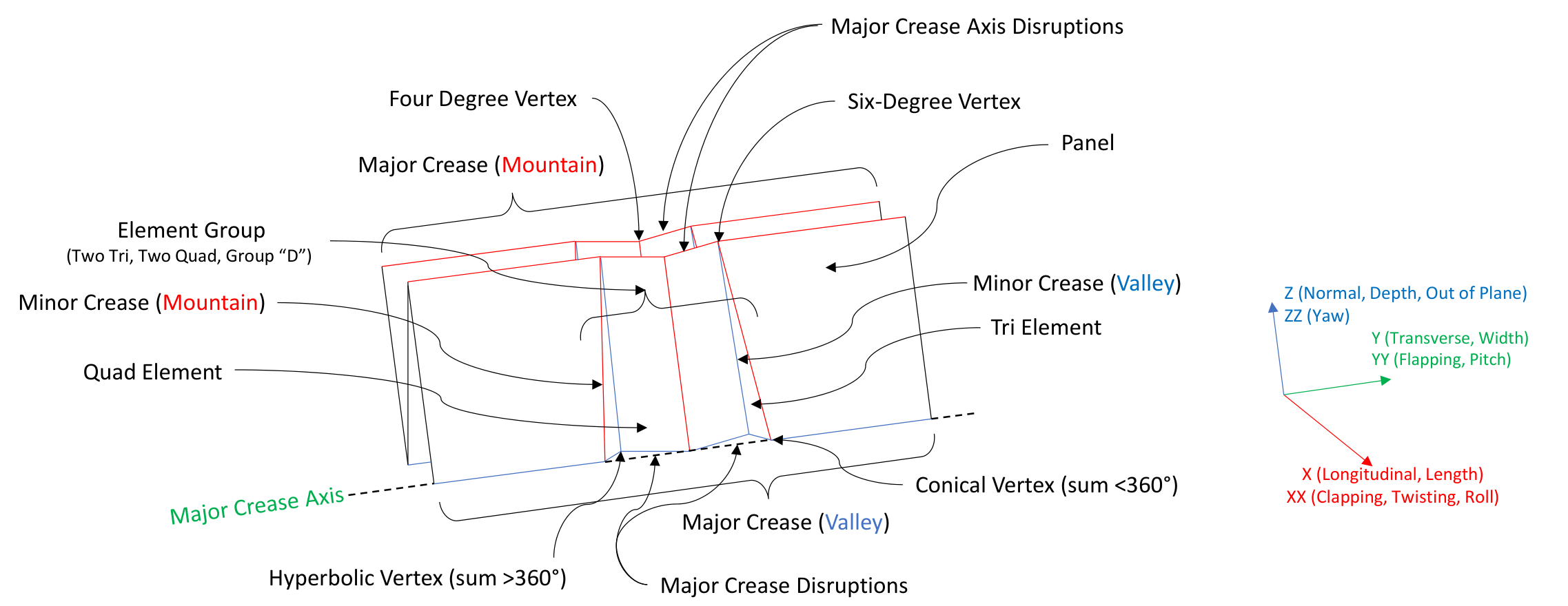
Major and minor creases define panels, elements, and their connections. The geometry distinguishes four- and six-degree vertices, conical vertices with angle sums below 360°, and hyperbolic vertices with sums above 360°. X, Y, and Z denote longitudinal, transverse, and normal directions.
Controlling the folding solution
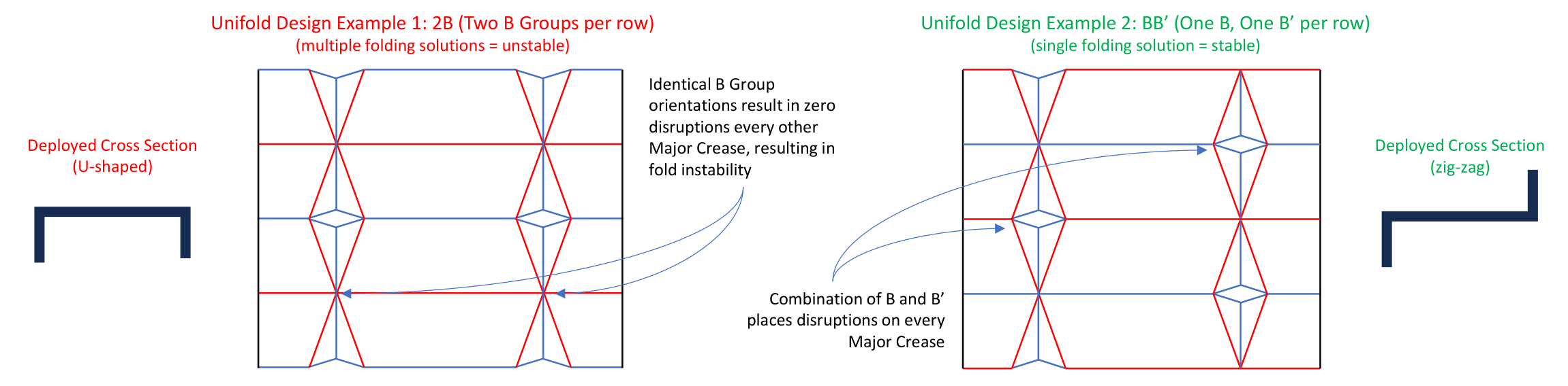
Group orientation matters as much as group selection. A prime denotes inversion: B′ is an inverted B group. Two identically oriented B groups leave every other major crease undisrupted and admit multiple folding solutions. Alternating B and B′ disrupts every major crease in the illustrated arrangement, producing a single folding solution. These disruptions place the kinematics within the active surface and interrupt locally developable bending paths.
Specifying sections and curvature
A, B, and C identify basic groupings. A configured design containing just one grouping is explicitly prefixed with 1: 1A, 1B, or 1C. Thus 1A denotes a design using one A grouping, while 2A places two A groupings side by side. The explicit count distinguishes the configured design from the grouping itself. CC′ pairs standard and inverted C groups; 2A2A′ combines two standard and two inverted A groups. Repeating BB′ can deploy into an eggbox tessellation. Group selection and crease angles determine the available deployed cross-sections.

Changing parallelism adds another degree of geometric control. Off-parallel major axes in Quad elements produce pitch curvature; off-parallel panel major creases produce yaw curvature during extension. Angle changes also permit flat, single-pleated, and dual-pleated surfaces, enabling loops and turns without introducing a separate structural framework.

Fabrication and deployed stability
The shell’s flat pattern includes cuts, making Unifold a kirigami structure. The manufacturing sequence uses those cuts to create a non-developable deployed surface from a flat assembly: openings span selected major creases, z-folding brings the disruption creases into alignment, and the aligned joints are bonded while folded. Re-expansion then articulates the complete crease network.
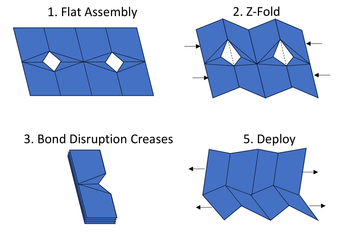
This sequence offers a route to eliminating discrete mechanisms while preserving flat-sheet fabrication. The economic opportunity lies in reducing the fabrication and assembly burden of deployment hardware. A cost floor below terrestrial solar is a proposed opportunity, not an established cost result.
Setting and retaining the deployed shape
Contact between elements limits joint over-rotation and sets the fully deployed state. The Unifold element shown below stops further opening through interference, unlike the dual-flat-folding reference. Interleaving extensions of adjacent panels can also resist Euler buckling of coplanar plates.
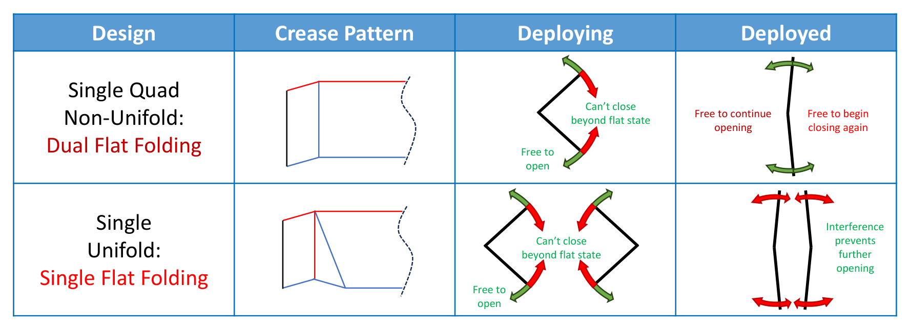
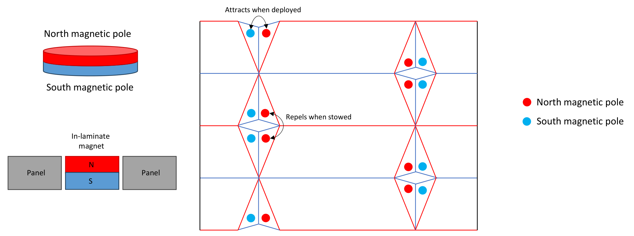
Magnetic forces can supplement that contact. Attraction between tangentially facing surfaces resists separation of folded thin rails and associated buckling. The proposed pole arrangement attracts when deployed and repels when stowed, initiating separation. This local deployment initiation does not supply all the energy needed to extend the complete aperture.
Prototype validation
Physical 2A prototypes tested the progression from making and articulating the laminated surface to arranging a larger deployed aperture. MK2 validated assembly and articulation using flight-like construction. MK3 extended the demonstration to local groupings positioning a global aperture.
MK2: laminate assembly and articulation
Garolite facesheets provided analogs for panel mass and stiffness. Continuous internal POE and ETFE layers spanned the panels and joints, forming living hinges between discrete Garolite panels. The resulting laminate was 1 mm thick.
The prototype successfully demonstrated assembly and articulation of the surface structure. The deployed photograph shows the structure under terrestrial gravity. The principal finding was the need to control spine-panel coplanarity to obtain the intended arrangement. [8]
Flat lamination
2A kirigami disruptions
Bonded and stowed
Deployed under 1 g
MK3: arranging a full aperture
MK3 used Garolite panels selected to represent the thickness, mass, and stiffness of incumbent low-cost solar module stacks, joined with 50 µm PET hinges. A 0.9 mm aluminum spine and magnetic panel latching supported the configured 2A assembly. It measured 3.1 m long × 1.5 m wide deployed and 9 mm thick when bonded and stowed. These dimensions and the hinge thickness incorporate the corrected prototype specifications.
| Quantity | Value |
|---|---|
| Deployed dimensions | 3.1 m long × 1.5 m wide |
| Equivalent solar area | 4.5 m² |
| Equivalent power at AM0 STC | 900 W |
| Mass-specific power | 120 W/kg |
| Stowed volumetric power density | 153 kW/m³ |
MK3 was a mechanical analog of this solar wing. The 900 W rating and specific-power figures describe equivalent photovoltaic performance at AM0 standard test conditions, rather than electrical output measured from the Garolite prototype. The stated 4.5 m² solar area is distinct from the 4.65 m² rectangular envelope given by its overall dimensions.
The demonstration established the ability of local groupings to articulate and position a global aperture at a flight-relevant scale. The project reported improved stiffness in the deployed configuration. The photographs document the flat assembly, compact stowed stack, and deployed front and rear surfaces; the supplied record does not quantify stiffness or specify the comparison baseline. [9]
Flat assembly
Bonded and stowed · 9 mm thick
Deployed front
Deployed rear
Together, the prototypes provide physical evidence for fabrication, articulation, and aperture arrangement. Their Garolite panels are mechanical analogs. The MK3 equivalent-wing figures above use its stated analog basis; the other solar performance estimates use the active-stack assumptions specified in their respective sections.
Design embodiments and applications
The same geometric family supports different aperture configurations. The following embodiments connect each crease pattern to its deployed form; the photovoltaic and radiator examples also show how active surfaces can occupy the resulting geometry.
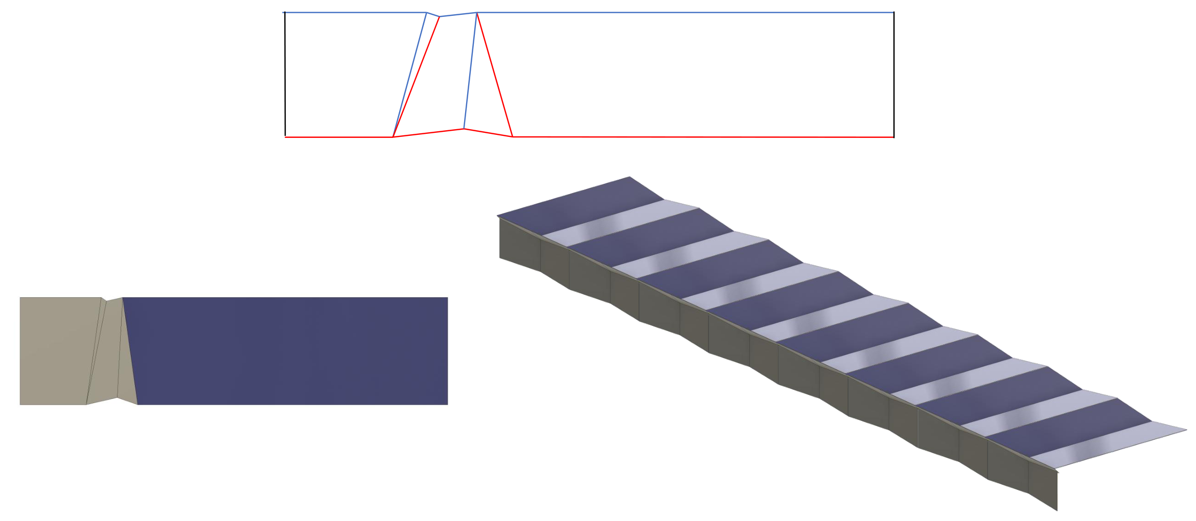
Aperture geometries: BB′, 1C, and 2A
BB′ uses alternating group orientation to obtain the shaped section described above. The 1C arrangement provides another section using a single C grouping. Both illustrate how structural depth can be incorporated within the surface itself.
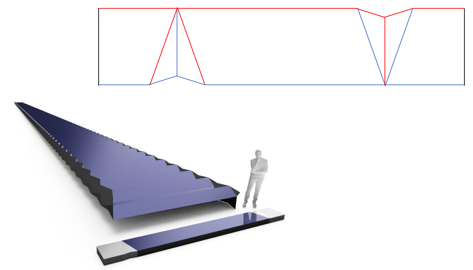
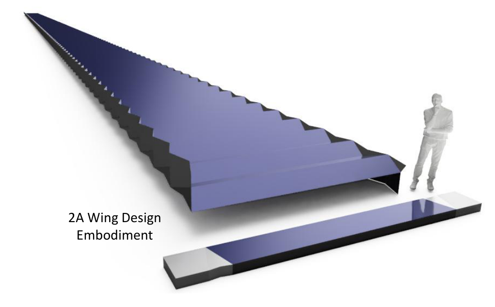
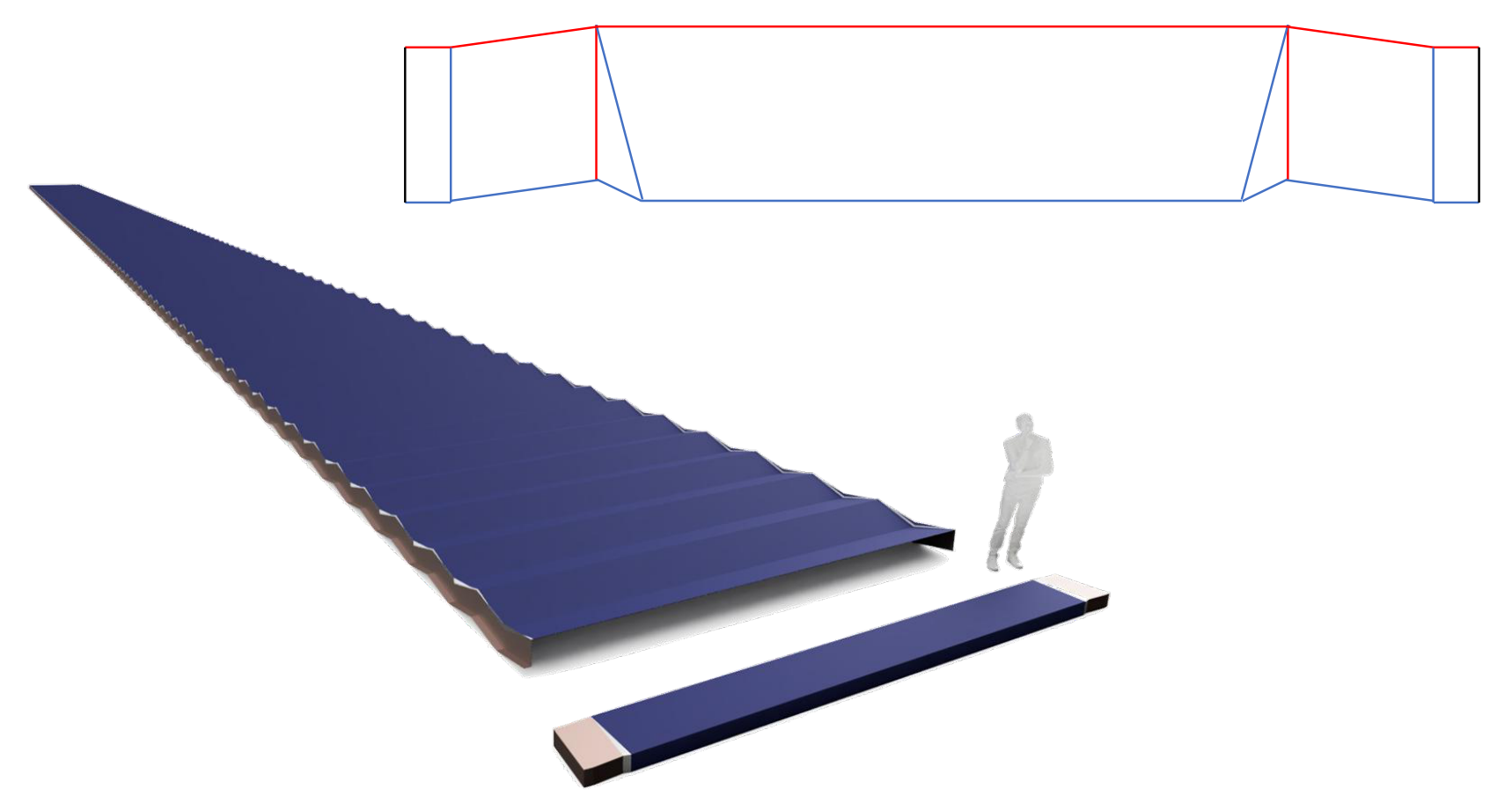
A further 2A embodiment places its groups near the outer edges of a broad central panel. It retains a large central active region while introducing section geometry along the wing. The deployed wing and its compact stowed stack are shown with a person for scale.
Performance of the 2A aperture
With uniform mass per unit area and a 90% active surface fraction, the 2A embodiment preserves 90% of the active stack’s mass-specific power: 0.90 × 225 = 202.5 W/kg. Combining 90% active surface with 90% packing of the stowed bounding volume preserves 81% of the stack’s volumetric performance: 0.90 × 0.90 × 321.4 = 260.4 kW/m³. These are surface-assembly estimates under the stated assumptions. The 90% and 81% factors describe performance retention: the active stack supplies the power, and the assembly preserves those fractions of its specific performance. Applying the same fractions to another solar technology would scale that technology’s own baseline in the same way. For radiators and antennas, the corresponding evaluation uses their functional output and integration requirements; the shared objective remains minimizing what the assembly takes away from the active surface. [7]
The source rounds the active-stack volumetric density to 320 kW/m³, giving 259.2 kW/m³, shown there as 259 kW/m³. Using the specified 0.7 mm thickness gives 260.4 kW/m³; both calculations use the same 81% retained volume fraction.
| Reference architecture | Mass per watt | Stowed volume per watt | Cost per watt |
|---|---|---|---|
| LEO telecom silicon boom and blanket | 72.2% reduction | 85.2% reduction | 50% reduction |
| GaAs ROSA or UltraFlex | Parity | 50% reduction | 99.75% reduction |
For the silicon benchmark, mass reduction is 1 − 56.25 / 202.5 = 72.2%, and volume reduction is 1 − 38.57 / 260.4 = 85.2%. The source comparison rounds these to approximately 75% and 85%. The 50% cost reduction assumes the blanket accounts for half of current assembly cost and the new architecture approaches blanket-only cost.
The GaAs ROSA/UltraFlex row preserves the source’s indicative comparison estimates. The supplied deck does not give the underlying GaAs baseline or cost build-up; those values are not derived from the common-stack calculation above. [7]
Functionally configured systems
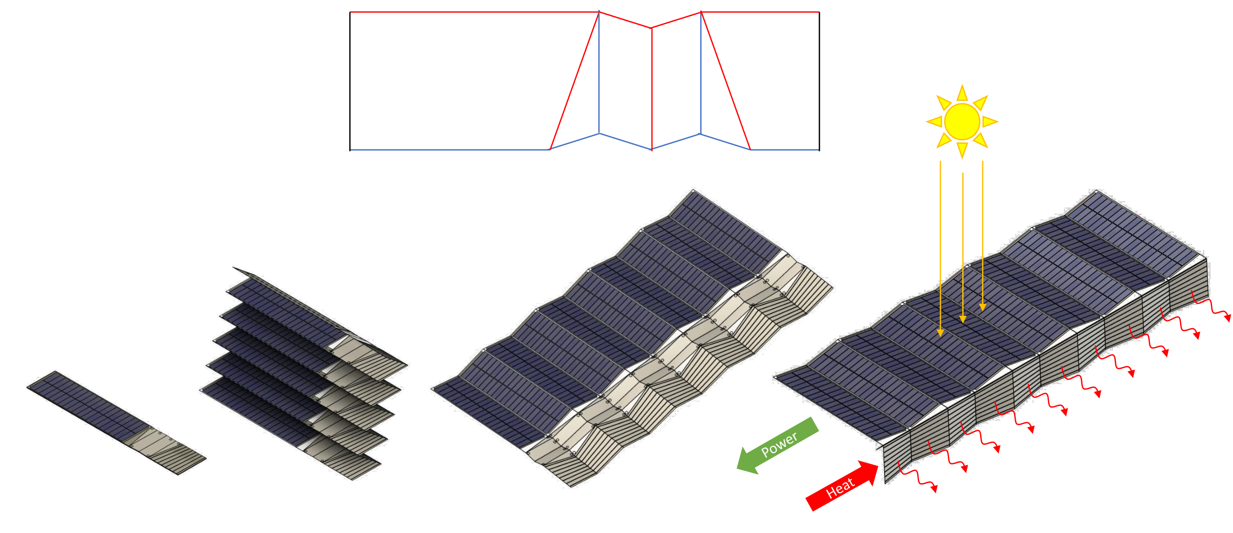
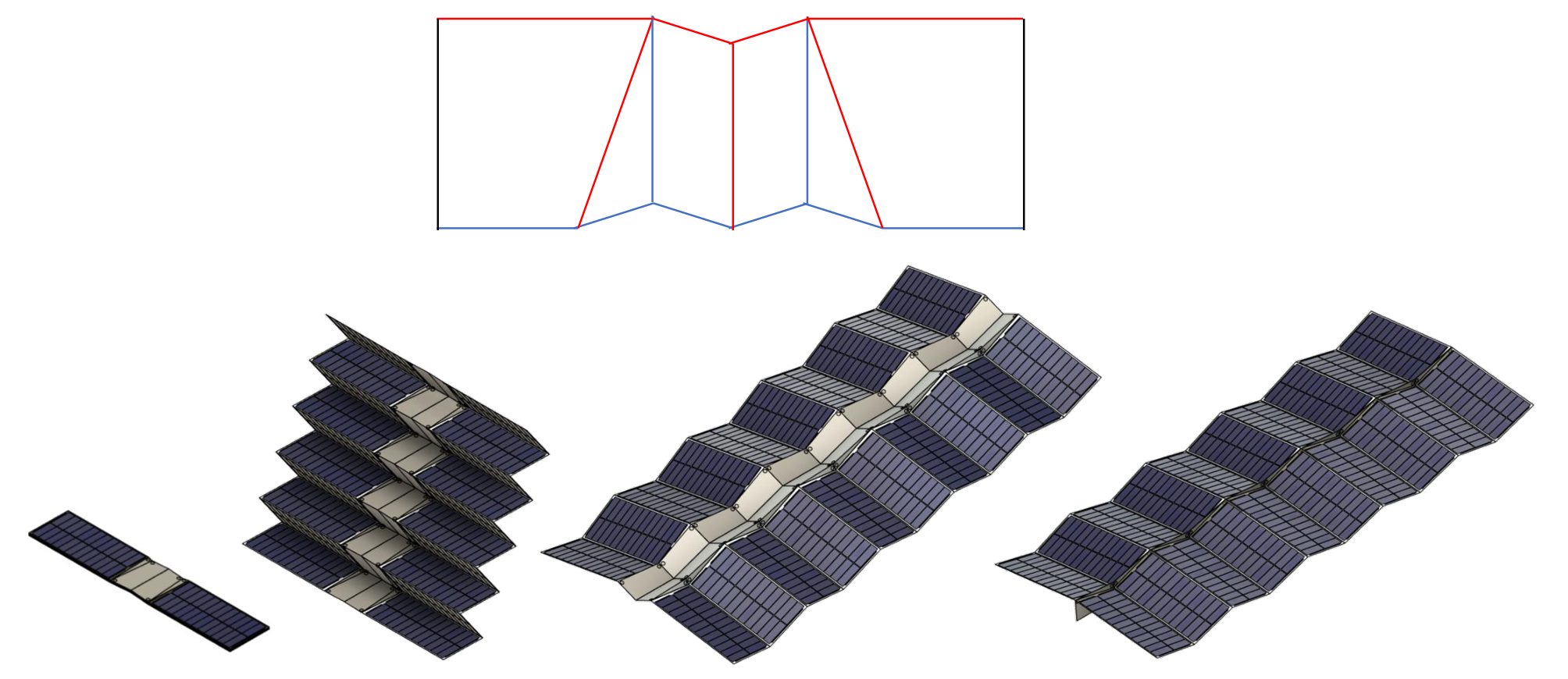
The 2A geometry can be configured as a functional system by incorporating photovoltaic and radiator surfaces. The examples below show combined power generation and heat rejection, followed by a photovoltaic-only configuration. The sequences show a compact stack opening into an aperture, with active regions carried by the panels. In the combined example, yellow rays indicate sunlight, the green arrow indicates electrical power, and red arrows indicate heat.
Concentration and aperture expansion
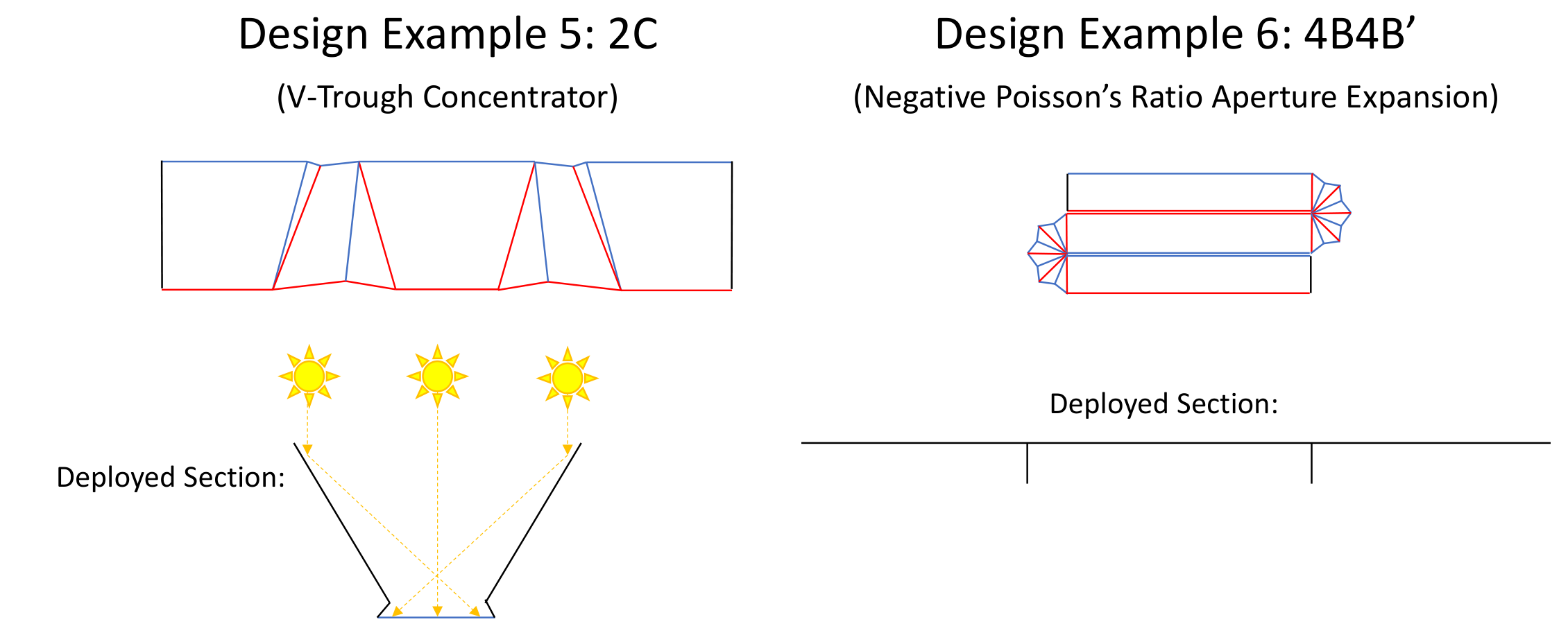
A 2C arrangement forms a V-trough concentrator. The 4B4B′ arrangement illustrates negative-Poisson’s-ratio aperture expansion. These embodiments extend the design space beyond the preceding wing configurations.
Comparison with other deployable surfaces
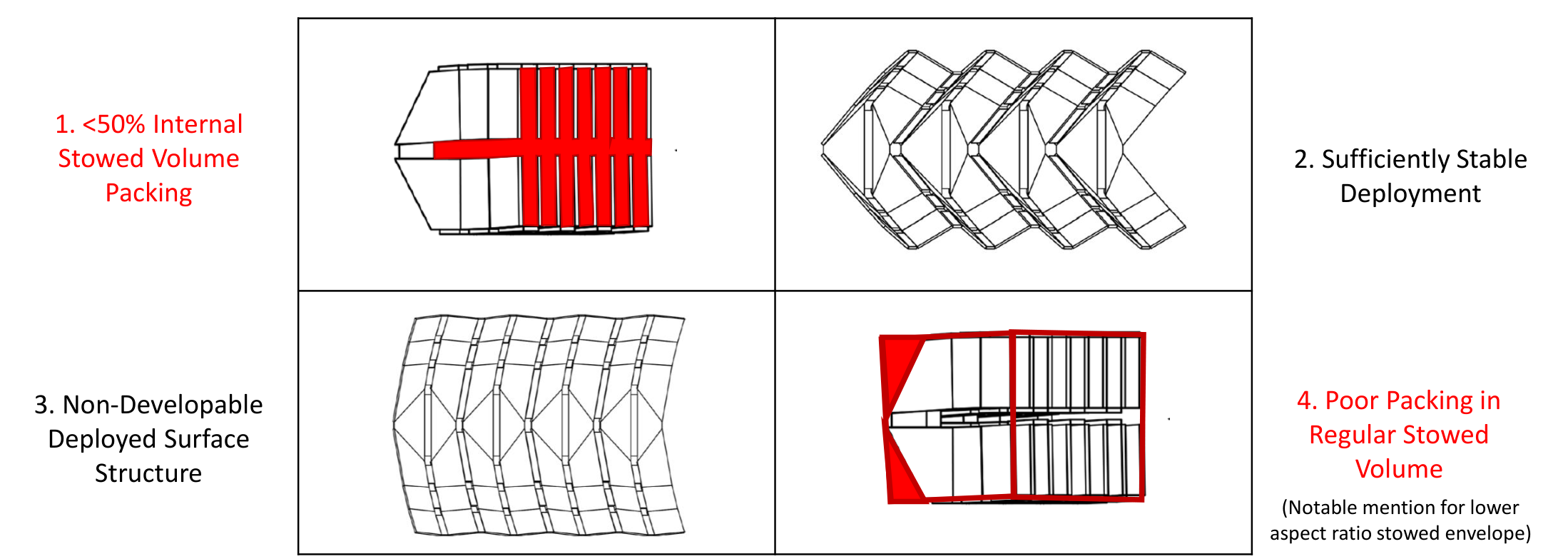
Alternative patterns illuminate the trade between packing, deployment control, and structural geometry. The comparisons below apply the same aperture requirements to each example. Red and green comparison annotations identify limitations and favorable attributes; the research sources for the underlying images remain attached to the figures.
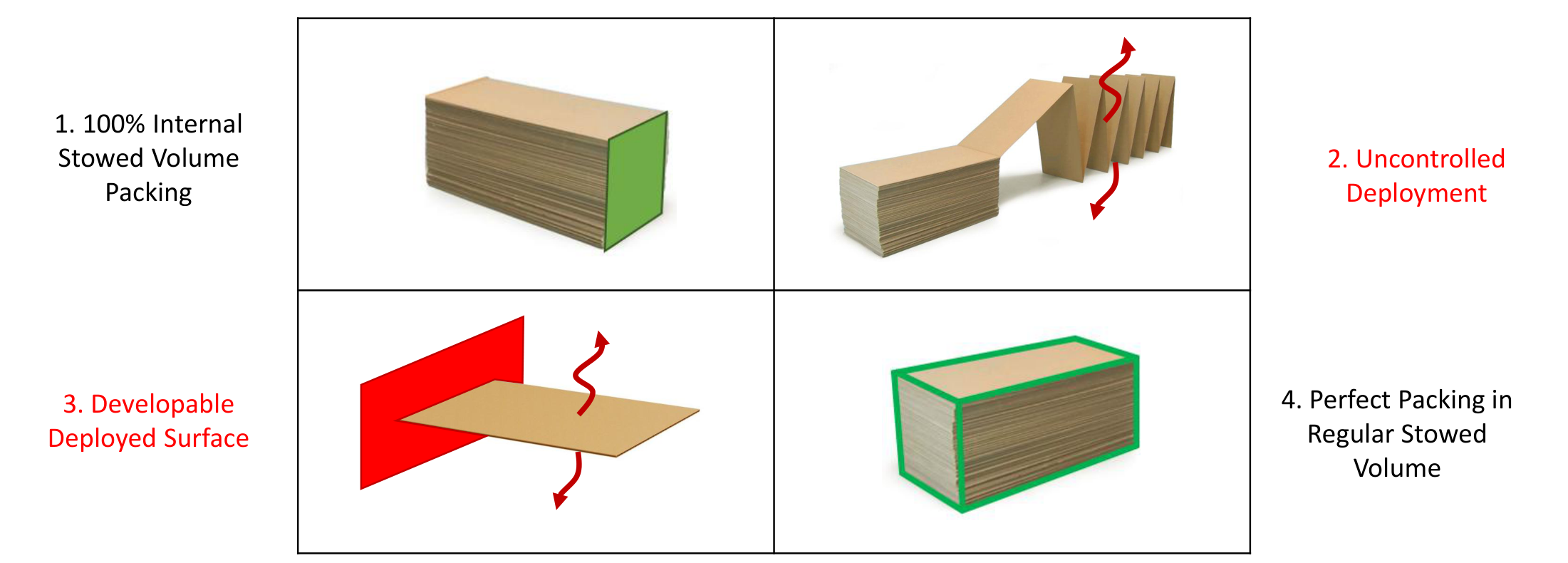
Z-fold
The z-fold packs both the active stack and its regular bounding volume efficiently. In the illustrated arrangement, deployment is uncontrolled and the deployed surface remains developable, leaving deformation modes resisted by weak local membrane bending.
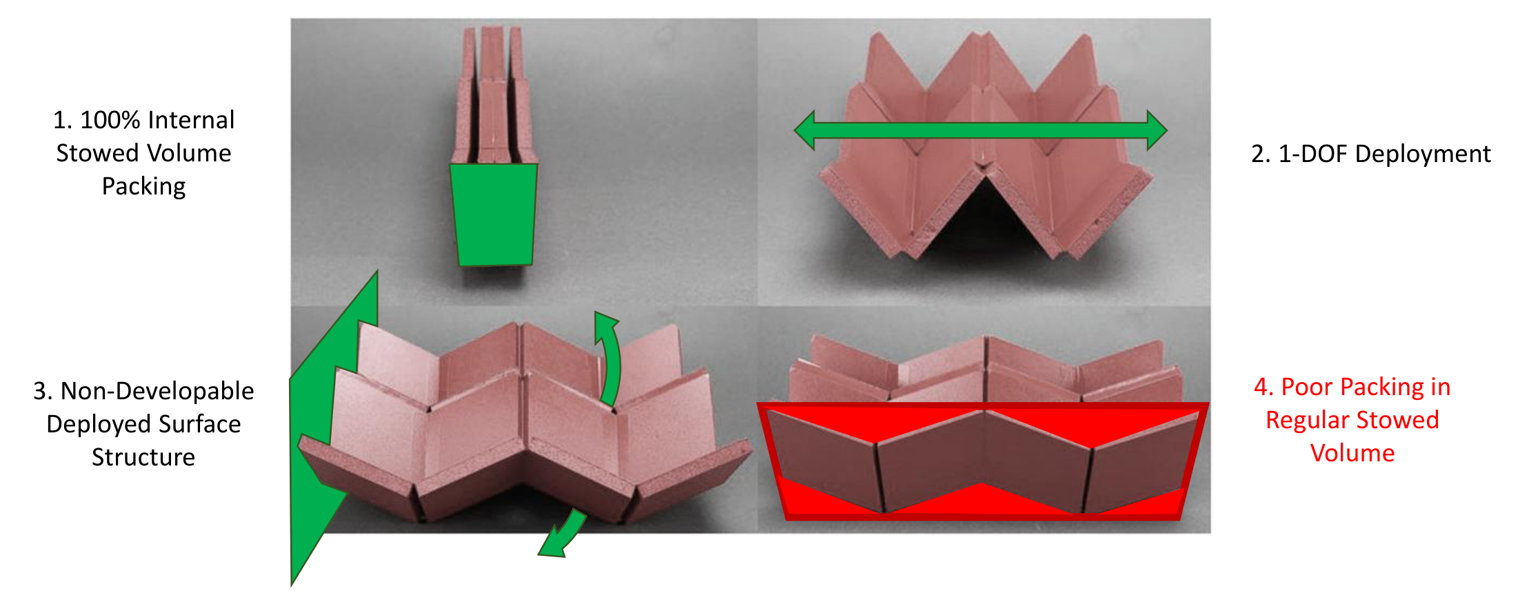
Eggbox
Eggbox combines efficient internal packing, one-degree-of-freedom deployment, and non-developable deployed geometry. Its irregular stowed envelope leaves unused space inside a regular bounding volume.
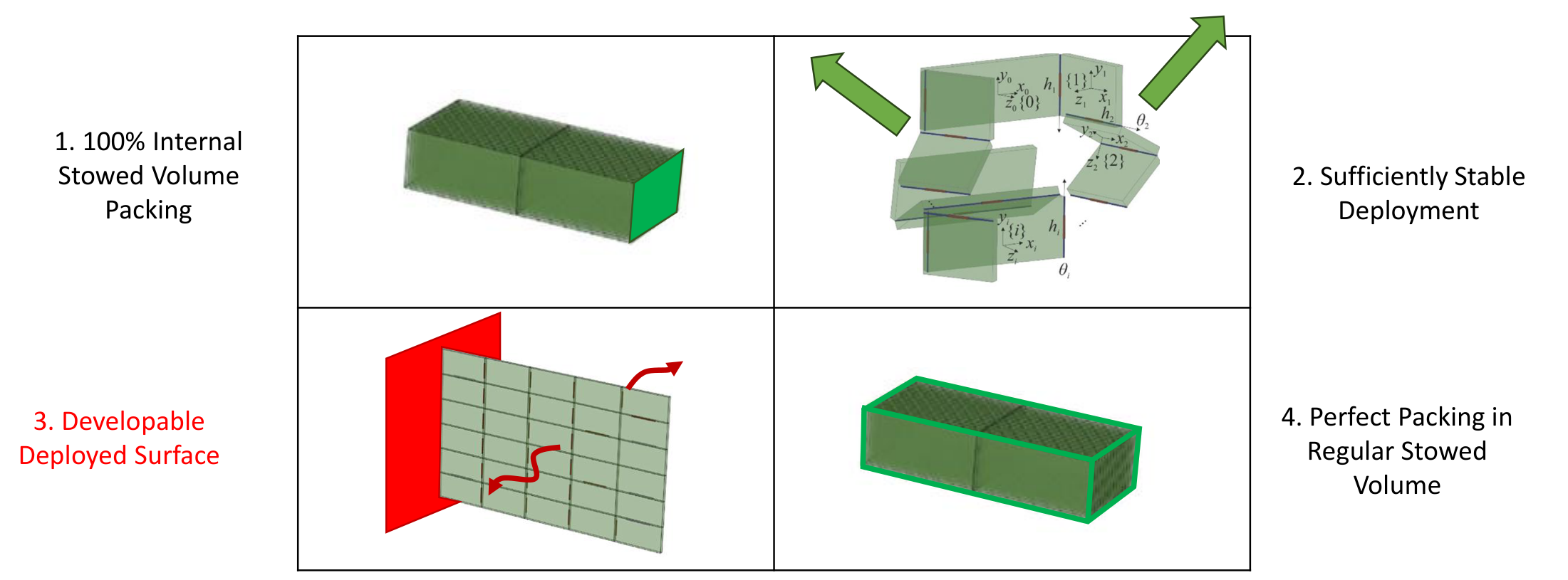
Hamiltonian circuit
The Hamiltonian-circuit example combines efficient internal and external packing with sufficiently stable deployment. The deployed surface remains developable, so deployment control does not resolve its thin-membrane local-bending weakness.
Yoshimura
The Yoshimura example similarly combines compact packing and sufficiently stable deployment, but retains developable geometry and local-bending paths rather than finite section depth throughout the aperture.
Waterbomb with eggbox
The waterbomb/eggbox combination provides non-developable structure and sufficiently stable deployment. Its internal stowed packing is assessed here as below 50%, and its external packing is poor within a regular bounding volume. A lower-aspect-ratio stowed envelope is a useful countervailing attribute.
Bloom patterns
Bloom patterns are radially expansive, developable, and flat-foldable. They offer another approach to compact surface deployment, but developability remains a limitation for the thin-membrane structural objective considered here.

Thick-panel origami
The three configurations below illustrate an approach to accommodating finite panel thickness. Offset-joint Miura-ori is among the alternatives whose extra mechanical complexity must be weighed against system-level performance.
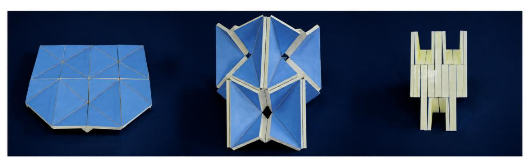
The design search need not be restricted to folding alone. Allowing cuts expands it to kirigami and enables the disruption-and-bonding approach used by Unifold. Simplicity is an optimization objective: geometric novelty should earn its place through improved system performance.
Engineering constraints
Unifold’s structural benefit comes from section geometry, but its material and joints remain flexible. Finite section depth provides a basis for stiffness; load capacity still depends on the material, connections, deployed geometry, and stability of the section.
Thickness and buckling
Unifold is generally a thin-folding solution. The intended structures have a 100–1,000× difference between membrane thickness and deployed structural scale, supporting the zero-thickness kinematic approximation described above while leaving finite-thickness accommodation as a practical constraint. Low panel and joint bending stiffness also permits Euler buckling of longitudinal stiffeners at intermediate loads.
Deployment assistance
Global deployment requires an applied driving influence. Candidate approaches include inertial deployment, gravity-gradient deployment, and hydraulic joint actuation inspired by insect wing and elytron deployment. These offer ways to extend the aperture without relying on sufficient elastic energy stored within the folded surface. Local magnetic repulsion may initiate opening; the selected assistance method must drive and control deployment of the full aperture. These are candidate deployment concepts for the space applications considered here.
The design objective is to approach the freely floating, flat active-surface ideal while providing only the deployment and structural function that the application requires. Reducing the requirement for self-arrangement can be more valuable than improving the structure used to satisfy it; where that requirement remains, the blanket’s own geometry can carry more of the burden. The illustrated configurations are embodiments of the articulated shell structure; they do not establish flight qualification or load ratings.
References and image credits
The references below credit the external imagery used in the design comparisons. Packing and deployment assessments are the author’s comparisons, not conclusions attributed to these papers. Unifold diagrams and design renderings are by Degrees of Freedom LLC.
- Alden Yellowhorse, Robert J. Lang, Kyler Tolman, and Larry L. Howell (2018). Creating Linkage Permutations to Prevent Self-Intersection and Enable Deployable Networks of Thick-Origami. Eggbox imagery.
- Jingyi Yang, Yunlan Zhang, Manolis N. Chatzis, and Zhong You (2022). Folding and deploying identical thick panels with spring-loaded hinges. Hamiltonian-circuit imagery.
- Yi Zhu and Evgueni T. Filipov (2024). Large-scale modular and uniformly thick origami-inspired adaptable and load-carrying structures. Yoshimura imagery. Author spelling follows the published paper.
- Long Huang, Peng Zeng, Lairong Yin, and Juan Huang (2022). Design of an origami-based cylindrical deployable mechanism. Waterbomb/eggbox imagery.
- Zhongyuan Wang, Robert J. Lang, and Larry L. Howell. Bloom patterns: radially expansive, developable and flat-foldable origami. Bloom-pattern image credit.
- Yan Chen, Rui Peng, and Zhong You. Origami of thick panels. Thick-panel image credit.
- Brian Ignaut, Degrees of Freedom LLC. Unifold Design Family Introduction, updated benchmark and 2A estimates. Benchmark imagery and assumptions: slide 3. 2A performance and comparative estimates: slide 24. Benchmark imagery credited in the deck to K2 Space promotional photographs and video captures.
- Degrees of Freedom LLC. MK2 Validation Prototype. Construction, assembly and articulation results, and prototype photographs.
- Degrees of Freedom LLC. MK3 Demonstration Prototype. Construction, aperture demonstration, and prototype photographs. Dimensions, hinge thickness, and equivalent-wing metrics in the text incorporate subsequent author corrections.